
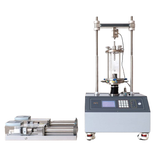
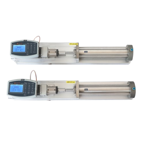
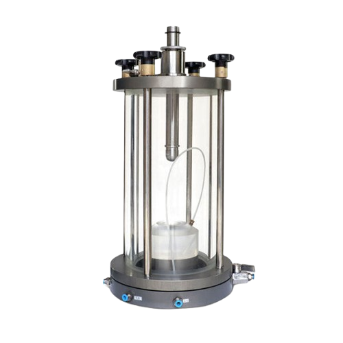
Automatic triaxial testing machine
Tình trạng: Hàng có sẵn
Nhà sản xuất: China
Mã hàng: TTS-1S
- Automatic triaxial testing machine, high quality and styles and design same with EU Brand ( similar GDS)
- Standard BS 1377-7- 8/ BS 1924-2/ ASTM D2850/ ASTM D 4767/ AASHTO T296; T297; TCVN 8868:2011
- Automatic triaxial testing machine doing testing UU, CU, CD and so on.
- The triaxial compression apparatus manages the entire testing process—from saturation through to shearing (CU, CD)—via computer-based software; users simply need to configure the program, and the test will run automatically from start to finish.
I/ What Is a Triaxial Test?
A triaxial test is a soil mechanics test used to determine the shear strength, deformation characteristics, and stress state of soil when the specimen is subjected to a stress condition that approximates actual in-situ conditions.
It is one of the most important tests for assessing the stability of foundations, slopes, levees, dams, roads, excavations, soft ground, and geotechnical structures.
1. Principle of the Triaxial Test
A cylindrical soil specimen is placed in a triaxial cell. The specimen commonly has a diameter of 38 mm or 50 mm and a height approximately twice its diameter.
Examples:
- D38 mm × H76 mm specimen.
- D50 mm × H100 mm specimen.
The specimen is enclosed in a rubber membrane and placed between two porous stones. The following steps are then performed:
- Apply cell pressure σ₃ around the specimen.
- Back pressure may be applied to saturate the specimen.
- Consolidate the specimen under a specified stress condition.
- After the required consolidation condition has been achieved, apply an axial load to the specimen.
- During shearing, the machine measures:
- Axial force;
- Axial deformation;
- Pore water pressure;
- Change in water volume, depending on the type of test.
- These measurements are used to calculate the stress, strain, and shear strength of the soil.
This can be understood in simple terms:
Cell pressure σ₃ → acts around the specimen
Axial load σ₁ → compresses the specimen from top to bottom
→ The soil specimen is subjected to a three-dimensional stress state; hence, the test is called a triaxial test.
2. Why Is a Triaxial Test Necessary?
In the field, soil is not subjected to a force in the vertical direction alone.
For example, a soil element beneath a foundation is simultaneously subjected to:
- Vertical stress;
- Horizontal stress;
- Pore water pressure;
- Structural loads;
- Stress changes caused by excavation or earth filling.
A triaxial test simulates this stress condition much better than a direct shear test.
The main objectives are to determine:
a. Shear Strength
This is a very important parameter for assessing whether soil may slide, fail, or become unstable.
The parameters commonly considered include:
- c′ – effective cohesion;
- φ′ – effective angle of internal friction;
- cu or su – undrained shear strength;
- φu – angle of internal friction in terms of total stress, depending on the test type.
b. Stress–Strain Relationship
This describes how soil deforms when subjected to loading.
For example:
- How much does the stress increase?
- How much deformation occurs?
- Is the soil stiff or soft?
- At what strain does the soil fail?
c. Pore Water Pressure
This is particularly important for saturated clay.
In CU and UU tests, changes in pore water pressure directly affect the effective stress and shear strength of the soil.
3. Basic Components of a Triaxial Testing System
An automatic triaxial testing system generally consists of the following main components:
3.1. Triaxial Cell
This is the chamber that contains the soil specimen. Water pressure is applied inside the cell to generate cell pressure σ₃.
Example: σ₃ = 280 kPa; this means that a pressure of 280 kPa acts around the specimen.
3.2. Soil Specimen
The specimen is generally cylindrical.
An example of a commonly used specimen size is D = 38 mm; H = 76 mm.
The ratio is H/D = 2, which is a very common specimen size for triaxial testing.
3.3. Rubber Membrane
The rubber membrane surrounds the specimen in order to:
- Prevent the cell water from coming into direct contact with the soil;
- Transmit cell pressure to the specimen;
- Hold the specimen in place during testing.
3.4. Porous Stones
These are placed above and below the specimen.
They allow water to pass through during saturation, consolidation, and pore water pressure measurement.
3.5. Piston
The piston applies an axial force to the specimen.
As the piston moves downward, the axial stress increases.
3.6. Load Cell
Measures the force applied to the specimen.
The axial stress can be calculated from this force: σ₁ = P/A
Where:
- P: axial force;
- A: corrected cross-sectional area of the specimen;
- σ₁: major principal stress.
3.7. Pore Water Pressure Transducer
Measures u during the test.
This is a particularly important parameter for saturated clay.
3.8. Pressure Controller
An automatic machine can control:
- Cell pressure;
- Back pressure;
- Pore water pressure;
- Loading rate;
- Strain rate;
- Water volume.
4. Three Main Stages of a Triaxial Test
For a CU test, the procedure can be divided into three major stages:
4.1. Stage 1 – Specimen Saturation
The purpose is to fill the voids in the soil specimen with water.
The following are commonly used:
- Cell pressure;
- Back pressure;
- B-value check.
Example: σ₃ = 280 kPa; back pressure = 230 kPa.
The pressure difference is therefore: σ₃ − uᵦ = 50 kPa.
Here, uᵦ is the back pressure.
After saturation, perform a B-check to assess the degree of saturation.
4.2. Stage 2 – Consolidation
After the specimen meets the saturation requirements, consolidation is carried out.
The purpose is to allow water to drain out of the specimen so that it reaches the desired stress state before shearing.
Example: σ₃ = 280 kPa; Back pressure = 230 kPa.
Pore water pressure may change when consolidation begins.
During consolidation:
Water drains out → specimen volume decreases → pore water pressure decreases → effective stress increases.
For soft clay specimens, this process may take a considerable amount of time.
Proceed to shearing only after the required consolidation condition has been achieved.
4.3. Stage 3 – Specimen Shearing
After consolidation is complete, axial loading is applied.
For a CU test, during the shearing stage:
Water is not allowed to drain out of the specimen.
The machine increases the load or deformation at the specified rate.
The following are recorded during shearing:
- Axial force;
- Deformation;
- Pore water pressure;
- Time;
- Cell pressure;
- Volume, if the system is equipped to measure it.
When the specimen reaches failure, the value of σ₁ − σ₃ at failure is obtained.
This is the deviator stress.
5. Common Types of Triaxial Tests
There are three important types:
5.1. UU – Unconsolidated Undrained
Simple procedure: Install specimen → apply cell pressure → shear immediately → do not allow drainage.
This test is suitable for rapid assessment of the undrained shear strength of soil under certain conditions.
Parameter of interest: cu / su.
5.2. CU – Consolidated Undrained
Procedure: Saturation → consolidation → undrained shearing.
This is a very important test for clay soils.
If pore water pressure is measured during shearing, the results can be analyzed in terms of both total stress and effective stress.
The following can generally be determined:
- c′;
- φ′;
- su;
- Stress–strain relationship;
- Pore water pressure.
5.3. CD – Consolidated Drained
Procedure: Saturation → consolidation → shearing under drained conditions.
The shearing rate must be sufficiently slow to allow excess pore water pressure to dissipate during shearing.
This test is commonly used to determine strength characteristics in terms of effective stress.
6. Comparison of UU, CU, and CD Tests
|
Test Type |
Consolidation |
Drainage During Shearing |
Main Information |
|
UU |
No |
No |
Undrained shear strength |
|
CU |
Yes |
No |
Total and effective stress, if u is measured |
|
CD |
Yes |
Yes |
Strength in terms of effective stress |
In geotechnical practice, CU and CD tests generally provide more information than UU tests. However, the test type must be selected based on the actual in-situ conditions of the soil and the requirements of the applicable standard/project.
7. Total Stress and Effective Stress
This is a very important concept for understanding triaxial testing.
According to the effective stress principle: σ′ = σ − u
Where:
- σ′: effective stress;
- σ: total stress;
- u: pore water pressure.
Example using values you previously provided:
- σ₃ = 280 kPa;
- u = 268.5 kPa.
Therefore: σ′₃ = 280 − 268.5 = 11.5 kPa.
This shows that, at that point, the horizontal effective stress was only about 11.5 kPa, even though the cell pressure was 280 kPa.
This is why, when interpreting triaxial test results, you should not look at σ₃ alone; u and the effective stress must also be considered.
8. Why Must Pore Water Pressure Be Measured?
Assume that during shearing: σ₃ = 200 kPa and u = 150 kPa.
Then: σ′₃ = 200 − 150 = 50 kPa.
If pore water pressure increases to 180 kPa: σ′₃ = 200 − 180 = 20 kPa.
Although the cell pressure remains unchanged, the effective stress has decreased.
This may significantly reduce the shear strength of the soil.
This phenomenon is particularly important in saturated clay, soft soil, and clayey mud.
9. Triaxial Test Result Curves
After the test is completed, the following curves are commonly plotted:
Stress–Strain Curve
X-axis: axial strain ε (%)
Y-axis: deviator stress q = σ₁ − σ₃
The curve is used to determine:
- Peak stress;
- Stress at a specified strain;
- Failure condition;
- Relative stiffness of the soil.
Pore Water Pressure Curve
X-axis: axial strain
Y-axis: u
This curve is particularly important for CU tests.
10. Determining Specimen Failure
The specimen does not always exhibit a clearly defined peak stress.
Failure may be determined according to the criteria in the applicable standard, for example, based on:
- Maximum deviator stress;
- Specified strain;
- Or another criterion specified for the soil type and test method.
When several specimens are tested under different cell pressures, Mohr circles can be plotted and the failure envelope determined.
This is then used to determine c and φ, or c′ and φ′, depending on the method of analysis.
11. Why Are Multiple Specimens Required?
A triaxial test program usually involves more than one specimen.
For example, three similar soil specimens may be tested using different cell pressures:
|
Specimen |
σ₃ |
|
Specimen 1 |
100 kPa |
|
Specimen 2 |
200 kPa |
|
Specimen 3 |
300 kPa |
After all three specimens have been sheared, the following values are obtained: σ₁; σ₃; q; u; ε.
These values are then used to determine the failure envelope and shear strength parameters.
12. Practical Applications of the Triaxial Test
The triaxial test is used in many types of geotechnical engineering analyses.
Foundations
Assessment of:
- Soil bearing capacity;
- Stability of soft ground;
- Settlement;
- Potential for shear failure.
Roads
Assessment of:
- Road subgrade;
- Embankment fill;
- Soft soil;
- Embankment slope stability.
Levees and Dams
Used to assess:
- Dam slope stability;
- Foundation stability;
- Resistance to sliding;
- Soil behavior as the water level changes.
Excavations
Used to assess:
- Stability of excavation walls;
- Risk of sliding;
- Deformation of soil around the excavation.
Structures on Soft Ground
Particularly important for:
- Clayey mud;
- Soft clay;
- Saturated clay;
- Soft soil near rivers;
- Soft soil in delta regions.
13. Testing a D38 × 76 mm Grey-Green Clayey Mud Specimen
For a CU test, the overall process can be illustrated as follows:
Obtain a D38 × 76 mm specimen
↓
Install the specimen in the triaxial cell
↓
Saturation
↓
B-check
↓
Consolidation
↓
Verify that consolidation is complete
↓
Close the drainage valves
↓
Undrained shearing
↓
Measure force + deformation + pore water pressure
↓
Determine σ₁, σ₃, q, and u
↓
Calculate effective stress
↓
Determine shear strength
↓
Combine results from multiple specimens to determine c′, φ′, or other applicable parameters.
14. Summary
The triaxial test can be understood as follows:
A cylindrical soil specimen is subjected to pressure around its circumference and then loaded vertically. This simulates the loading condition of soil in the field and allows measurement of specimen deformation, failure behavior, and the generation of pore water pressure.
For a CU test, the three most important stages are:
SATURATION → CONSOLIDATION → UNDRAINED SHEARING
Where:
- Saturation → removes the influence of air in the soil voids.
- Consolidation → brings the specimen to the desired stress state.
- Shearing → determines the shear strength and behavior of the soil.
For a D38 × 76 mm grey-green clayey mud specimen, particular attention should be paid to the B-value during saturation, the criteria for completion of consolidation, the CU shearing rate, and the development of pore water pressure u.
II/ What Is an Automatic Triaxial Compression Testing Machine?
An Automatic Triaxial Compression Testing Machine is used in soil mechanics testing to determine the shear strength and deformation characteristics of soil under stress conditions that simulate those encountered in actual foundations and engineering structures.
1. Main Functions
The main functions of an automatic triaxial compression testing machine include:
- Generating and maintaining cell pressure uniformly around the soil specimen in the horizontal direction.
- Applying back pressure to saturate the soil specimen before testing.
- Measuring pore water pressure during consolidation and shearing.
- Automatically controlling the consolidation process and monitoring volume changes or the amount of water draining from the specimen.
- Automatically applying axial loading at a preset strain rate or loading rate.
- Measuring axial deformation, axial force, cell pressure, pore water pressure, and other relevant parameters.
- Automatically recording and storing data over time, reducing errors caused by manual data recording by the operator.
- Depending on the machine configuration and control software, common triaxial tests such as UU, CU, and CD can be performed.
2. Purpose of the Machine
The primary purpose of the machine is to determine the bearing capacity, shear strength, and deformation characteristics of soil.
The tests can be used to determine or calculate parameters such as:
- Cohesion – c
- Internal friction angle – φ
- Undrained shear strength – Su
- Stress–strain relationship
- Pore water pressure
- Effective stress parameters
- Consolidation and deformation characteristics of soil
- Parameters used to construct the Mohr–Coulomb failure envelope.
3. How Does the Machine Work?
Basically, a cylindrical soil specimen is placed inside the triaxial cell. The machine applies cell pressure around the specimen and then applies an axial load.
The process generally consists of:
Specimen preparation → specimen installation → application of cell pressure → saturation → consolidation → shearing → recording force, deformation, and pore water pressure → processing the results.
An important feature of an automatic machine is that pressure application, loading, measurement, and data recording are controlled by an electronic system/software. This helps make testing more stable and repeatable than manually operated systems.
4. What Is the Machine Used for in Practice?
Results obtained from a triaxial compression testing machine are used for:
- Foundation design
- Assessment of soil bearing capacity
- Slope stability calculations
- Road subgrade stability analysis
- Design and assessment of levees, dams, and soft ground
- Stability analysis of earth structures
- Calculation of earth pressure on retaining walls
- Research on soft soil, clay, clayey mud, and saturated soil
- Determination of input parameters for geotechnical analysis models.
5. What Makes an Automatic Triaxial Machine Different?
Compared with semi-automatic or manually operated triaxial equipment, an automatic system offers the major advantage of accurately controlling the testing process. This is particularly important for soft soil or clay specimens, for which cell pressure, back pressure, pore water pressure, strain rate, and consolidation must be carefully controlled.
III/ Below are the detailed specifications of an automatic triaxial testing machine:
Automatic Triaxial Compression Testing Machine Model: TTS-1
* System Functions:
- Complies with the following standards: BS 1377-7 / BS 1377-8 / BS 1924-2 / ASTM D2850 / ASTM D4767 / AASHTO T296; T297;
- This triaxial testing system uses advanced technology and integrates mechanical and electronic technologies. It is fully automated and performs automatic measurements using sensors. The loading frame is designed to operate either as part of a computer-controlled triaxial system or as a standalone unit.
- The equipment includes:
+ Loading frame,
+ Advanced Pressure/Volume Controller (APVC),
+ Triaxial cell,
+ Sensors,
+ AdvancedGeoLAB® software.
- Single-cell configuration, for specimens with a diameter of Ø 38 mm.
- Automatically performs the following independent triaxial tests from start to finish:
+ UU test (Unconsolidated–Undrained): Unconsolidated-undrained test.
+ CU test (Consolidated–Undrained): Consolidated-undrained test.
+ CD test (Consolidated–Drained): Consolidated-drained test.
* Loading frame capacity: 10 kN or higher (optional: 30 kN, 50 kN, or 100 kN).
Functions:
- The triaxial loading frame is rigid, durable, low-noise, and operates smoothly. It uses a stepper motor combined with a worm-gear drive system. The machine is equipped with upper and lower limit devices; axial deformation is measured and recorded by a high-precision displacement sensor.
- Axial load is measured by a load cell. An overload protection device automatically stops the machine if the applied axial force exceeds the load cell's measurement range.
- LCD digital display.
- 16-key keypad.
Technical Specifications:
- Maximum loading capacity: 10 kN.
- Built-in displacement transducer with a 25 mm range and a resolution of 0.01 mm.
- Two measurement channels for load (load cell) and pore-water pressure (pore pressure).
- One USB port for connection to a computer.
- Compatible specimen size: Ø 38 mm × 76 mm (H). Larger loading frames can accommodate larger specimens.
- Loading rate range: 0.00001–9.99999 mm/min.
- Accuracy: ±0.1% FS (full scale).
- Test height: approximately 450 mm.
- Distance between the two columns: approximately 240 mm.
- Loading platen diameter: 96 mm.
- Ports provided for load-cell and computer connections.
- Dimensions: 430 × 370 × 1030 mm.
- Power supply: 110–240 VAC, single-phase, 50 Hz.
- Weight: approximately 45 kN.
* Cell Pressure / Volume Controller (Cell Pressure)
- USB connection.
- LCD display with a 16-key keypad.
- Maximum cell pressure: 2 MPa (1 kPa resolution) [3 MPa optional].
- Maximum volume: 100 ml (0.001 ml resolution) [250 ml optional].
- Overpressure and over-volume protection.
* Back Pressure / Volume Controller (Back Pressure)
- USB connection.
- LCD display with a 16-key keypad.
- Maximum back pressure: 2 MPa (1 kPa resolution) [3 MPa optional].
- Maximum volume: 100 ml (0.001 ml resolution) [250 ml optional].
- Overpressure and over-volume protection.
* Triaxial Test Cell (larger cell available as an option)
Construction
Consists of: cell base; cell body; top cap; cell wall; loading rod.
- The cell is secured with quick-release clamps for easy assembly and disassembly.
- The bottom of the cell has four connection ports:
+ Pore-water pressure (Pore Pressure).
+ Cell pressure (Cell Pressure).
+ Back pressure (Back Pressure).
+ Water inlet to the cell.
- Maximum cell pressure: 2 MPa.
- Suitable for specimens measuring Ø 38 × 76 mm.
- Dimensions: Ø 160 × 310 mm.
- Weight: 8 kg.
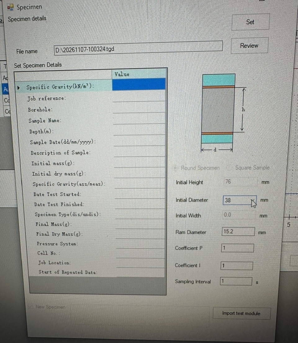
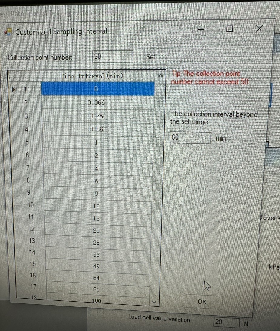
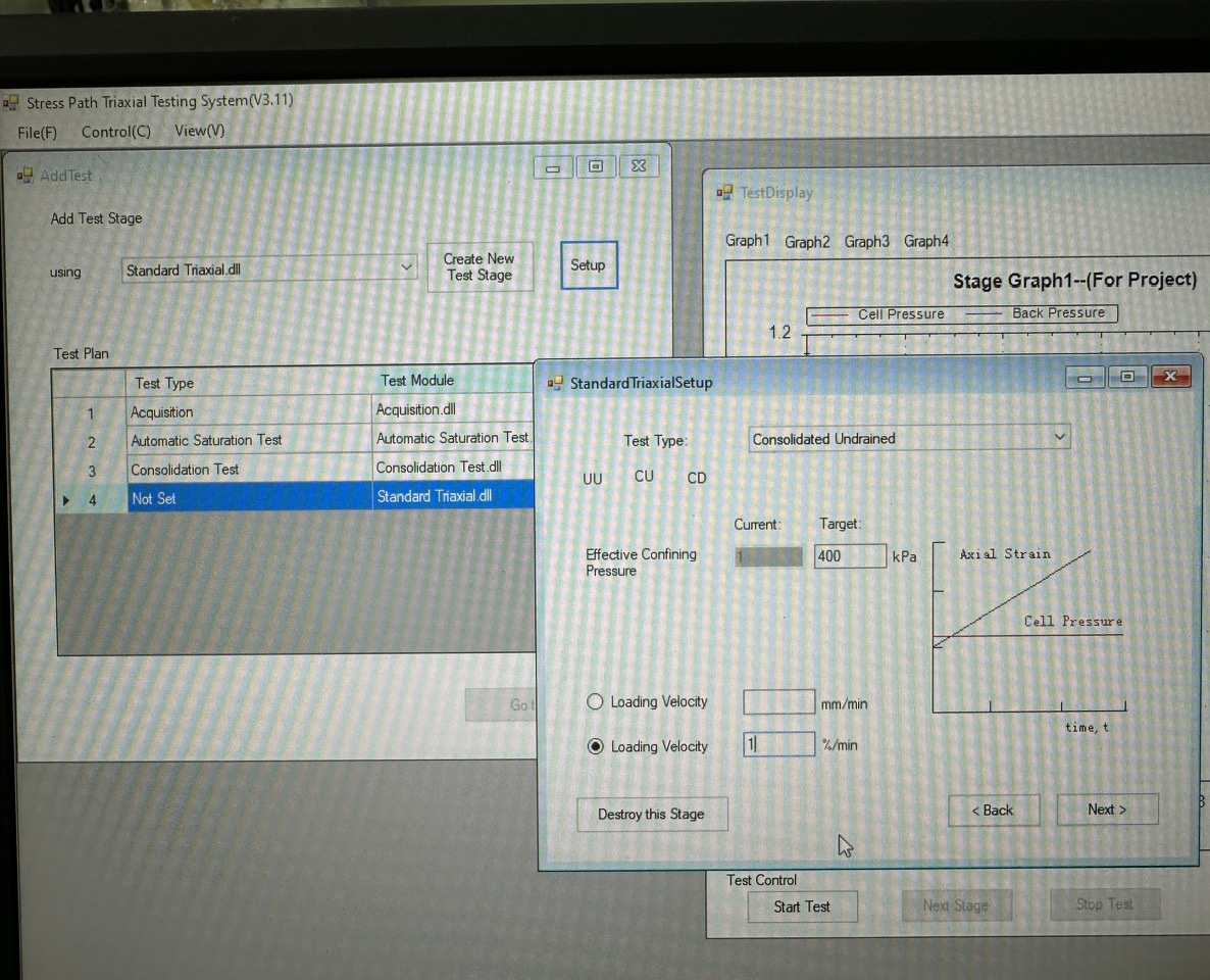
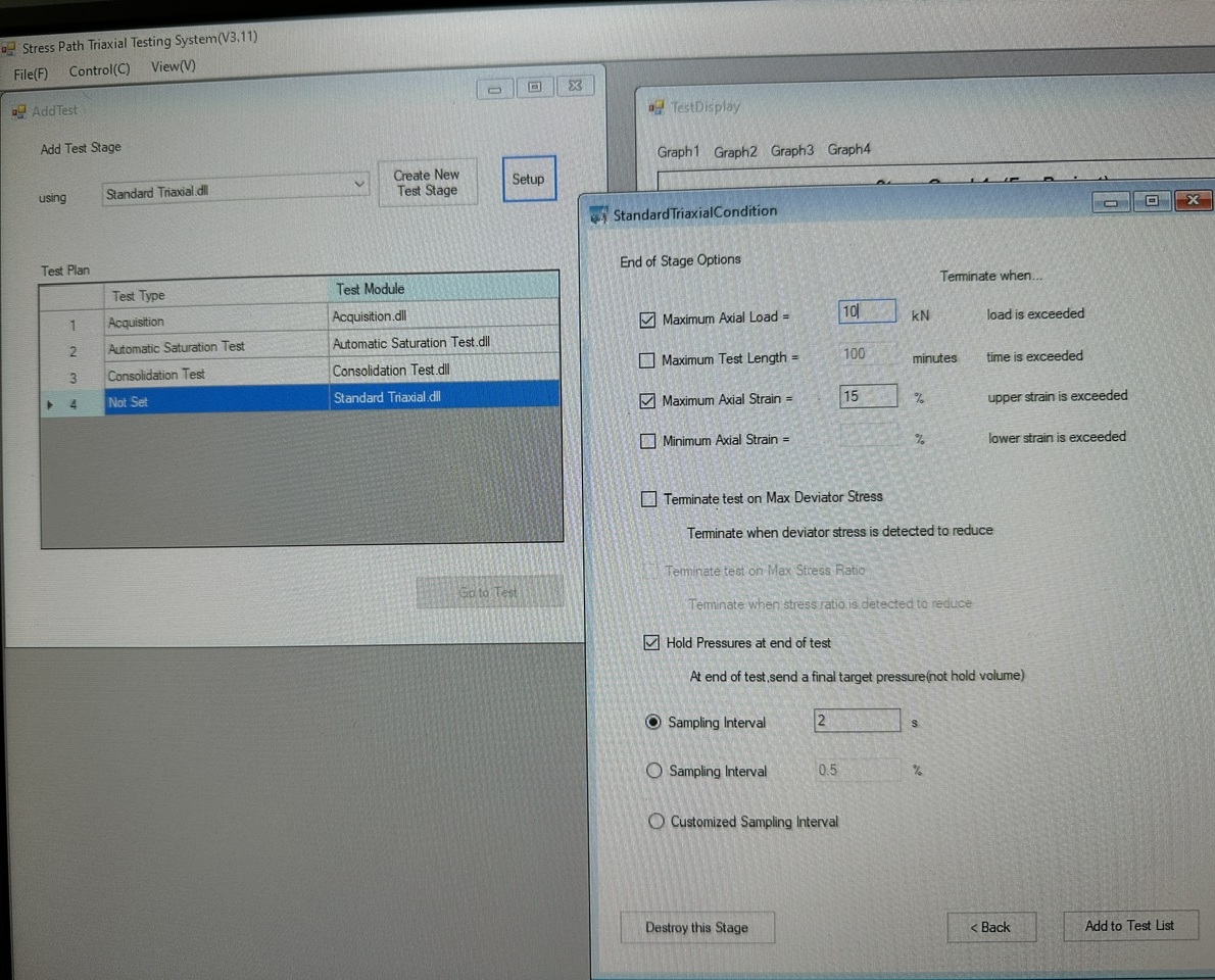
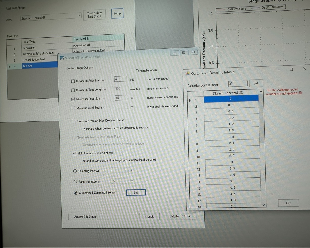
* Triaxial Testing Software
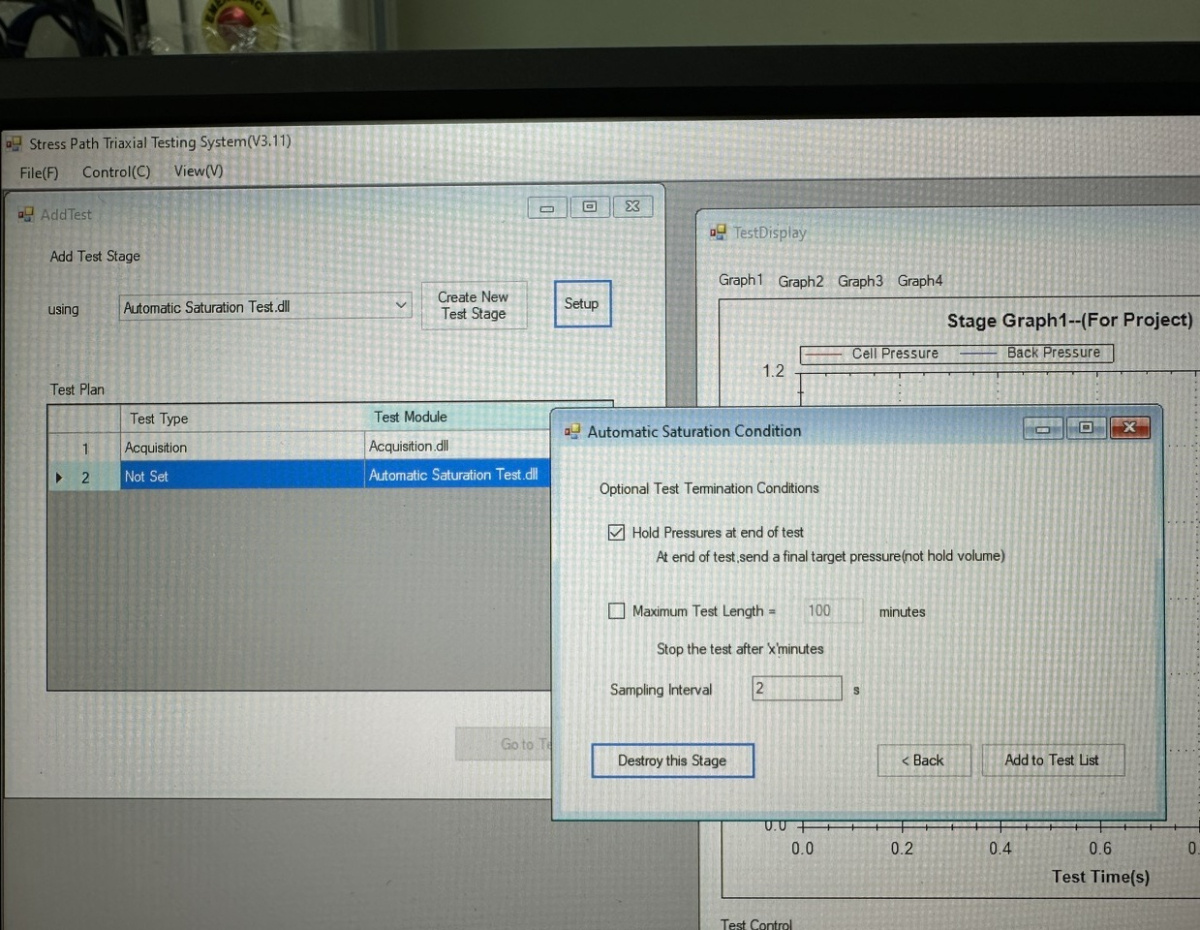
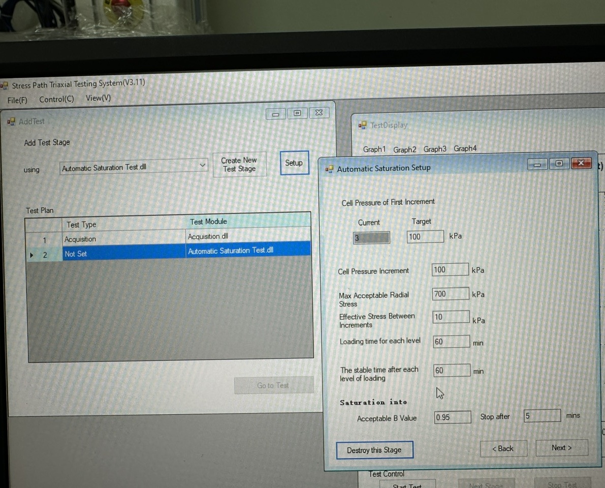
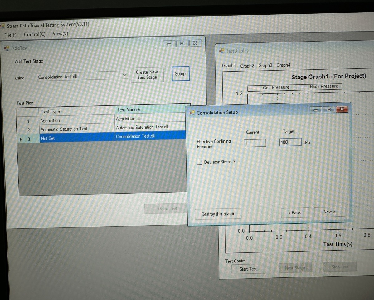
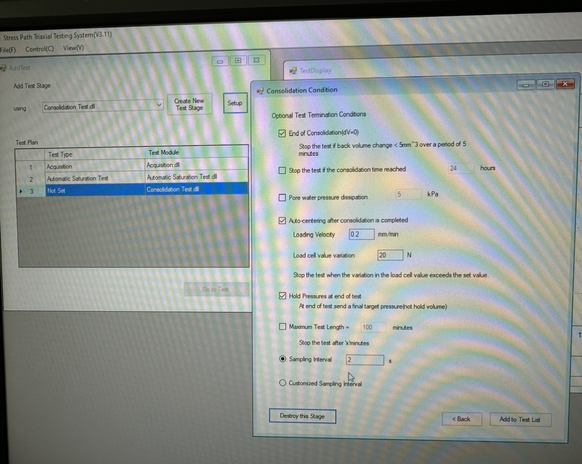
+ The triaxial testing software is an essential part of soil triaxial testing. It simulates soil tests in accordance with international standards, covering the stages from specimen saturation and B-check through consolidation and CU or CD shearing.
+ Each test stage has its own termination criteria. Once the specified requirements are met, the software automatically proceeds to the next stage until the test program is completed.
+ After the program is completed, users can review the test data for each stage by exporting the data to Excel. The software can also plot graphs and determine the cohesion intercept (c′) and angle of internal friction (φ′) after all three specimens have been tested.
+ The software monitors, measures, and displays key values, including pore-water pressure (pore pressure), cell pressure, back pressure, axial compressive force (load cell), and other parameters throughout the test.
Available functions:
- Data acquisition module.
- Automatic specimen saturation and B-check module.
- Consolidation.
- Triaxial tests: UU, CU, and CD.
Sản phẩm liên quan


Máy nén nở hông YYW-2
Liên hệ

Thí nghiệm trương nở đất WZ-2
Liên hệ


Súng bật nẩy bê tông Matest C380
Liên hệ

Máy siêu âm bê tông Matest C369N
Liên hệ


Sản phẩm cùng hãng
Máy nén nở hông YYW-2
Liên hệ
Thí nghiệm trương nở đất WZ-2
Liên hệ

Bình tỷ trọng đất 100ml
Liên hệ

Máy thử thấm bê tông HS-4
Liên hệ
 Khuyến mãi


Bể ổn nhiệt Marshall HHW-2
Liên hệ

Máy nén marshall LWD-1
Liên hệ

Hóa mềm tự động LD-2000
Liên hệ
